555 Timer Schematic - The History of 555 Timer IC - Story of Invention : In this video we look at a simple 555 astable circuit.. A monostable 555 timer is required to produce a time delay within a circuit. The timer's internal circuitry is largely responsible for this triggering but it is also caused stray or installed capacitance at the trigger input of the timer. 555 datasheet 555 duty cycle 555 metronome 555 reset function 555 time delay relay inverted 555 timer pulse generator. Being an integral part of electronics project, 555 timer ic is very often used in simple to complex electronics projects. 555 ic timer block diagram 555 ic timer block diagram.
The standard 555 timer ic is made of 2 diodes. Working modes of 555 timer ic. The working modes of a 555 timer are astable, bistable, and monostable. The 555 timer is a chip that can be us… As you might already know, a 555 timer can be easily wired as astable, monostable or bistable multivibrator.
555 timer bassed Electronic lock circuit with explanation ... from 4.bp.blogspot.com Adjustable on off timer(using 555 astable mode) in this circuit a timer with cyclic on off operations is designed. 555 timer is an industrial standard ic existing from early days of ic. This tutorial provides sample circuits to set up a 555 timer in monostable, astable, and bistable modes as well as an in depth discussion of how the 555 timer works and how to choose components to use with it. These on off intervals can be adjusted by varying the 555 timer output and number of counter outputs. The 555 timer is a chip that can be us… We connect a 100μf capacitor to the positive voltage supply and then to pin 2. We have seen in the last few tutorials that the 555 timer can be configured with externally connected components as multivibrators, oscillators and timers, with timing intervals ranging from a few microseconds to many hours. Lm555 timer 1 features 3 description the lm555 is a highly stable device for generating 1• direct replacement for se555/ne555 accurate time delays or oscillation.
Its name is derived from three 5k ohm resistors ,connected in series used in it.the timer ic can produce required waveform accurately.
555 timer is an industrial standard ic existing from early days of ic. The block diagram of a 555 timer is shown in the above figure. We connect a 100μf capacitor to the positive voltage supply and then to pin 2. Also, 555 timer is used to generate an oscillating pulse. Daman shah june 5, 2021. We have a large collection of simple and advanced projects using 555 timer ic. The circuits explained here are 10 best small timer circuits using the versatile chip ic 555, which generates predetermined time intervals in response to momentary input triggers. 555 timer circuits (133) browse through a total of 133 555 timer circuits and projects including the timer's datasheet. The breadboard schematic of the above circuit is shown below. Working modes of 555 timer ic. 555 timer was first introduced by signetics corporation in 1971 as se555/ne555. We have seen in the last few tutorials that the 555 timer can be configured with externally connected components as multivibrators, oscillators and timers, with timing intervals ranging from a few microseconds to many hours. The 555 ic timer circuit above shows a very straightforward design where the ic 555 forms the central controlling part of the circuit.
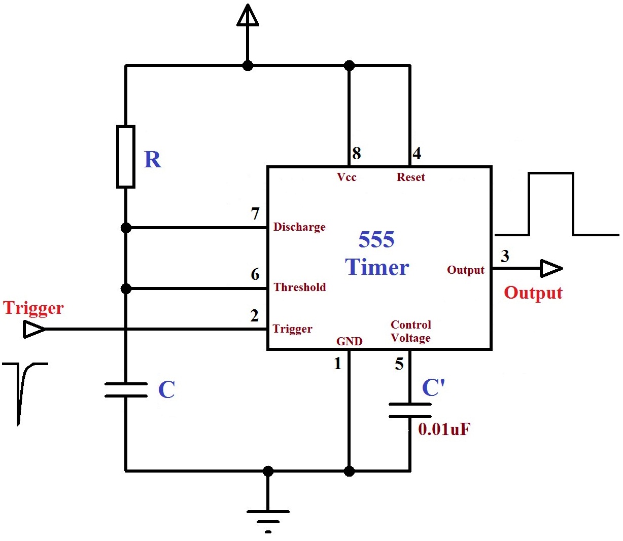
In this video we look at a simple 555 astable circuit. As you might already know, a 555 timer can be easily wired as astable, monostable or bistable multivibrator. As discussed in the above section, the ic is in its standard monostable mode. 555 timer circuits (133) browse through a total of 133 555 timer circuits and projects including the timer's datasheet. If a 10uf timing capacitor is used, calculate the value of the resistor required to produce a minimum output time delay of 500ms.
Monstable Multivibrator using 555 Timer from electrosome.com The 555 timer can be used with a supply voltage (vs) in the range 4.5v to 15v (18v is. Additional • timing from microseconds through hours terminals are provided for triggering or resetting if • operates in both astable and monostable modes desired. 555 timer circuits (133) browse through a total of 133 555 timer circuits and projects including the timer's datasheet. There are simple circuits for beginners and advanced engineers. Once this switch is pushed, the circuit pulls its output to a. In this mode, the circuit of the ic 555 timer produces the continuous pulses with exact frequency primarily based on the value of the two resistors and. If a 10uf timing capacitor is used, calculate the value of the resistor required to produce a minimum output time delay of 500ms. This circuit uses very basic components like 555 timer and 4017 counter.
Rain alarm using 555 timer.
Rain alarm using 555 timer. In this mode, the circuit of the ic 555 timer produces the continuous pulses with exact frequency primarily based on the value of the two resistors and. The general 555 timer circuit schematic at the heart of the circuit is a lm555 ic, which includes 23 transistors, 2 diodes and 16 resistors on a silicon. Additional • timing from microseconds through hours terminals are provided for triggering or resetting if • operates in both astable and monostable modes desired. The breadboard schematic of the above circuit is shown below. We have seen in the last few tutorials that the 555 timer can be configured with externally connected components as multivibrators, oscillators and timers, with timing intervals ranging from a few microseconds to many hours. The values of r1 and c1 determine how long the output will remain high. The 555 timer can be used with a supply voltage (vs) in the range 4.5v to 15v (18v is. The 555 timer ic is an integrated circuit (chip) used in a variety of timer, delay, pulse generation, and oscillator applications. Once this switch is pushed, the circuit pulls its output to a. 555 timer circuits (133) browse through a total of 133 555 timer circuits and projects including the timer's datasheet. 555 timer was first introduced by signetics corporation in 1971 as se555/ne555. Its name is derived from three 5k ohm resistors ,connected in series used in it.the timer ic can produce required waveform accurately.
This circuit can be used as rain sensor, water overflow sensor or as a water level sensor. The 555 timer ic is an integrated circuit (chip) used in a variety of timer, delay, pulse generation, and oscillator applications. The timer's internal circuitry is largely responsible for this triggering but it is also caused stray or installed capacitance at the trigger input of the timer. Let us discuss in detail about this circuit. The block diagram of a 555 timer is shown in the above figure.
Pin on 555 Timer Circuits from i.pinimg.com Here is a simple and interesting hobby circuit that can be made using the popular 555 timer ic. The working modes of a 555 timer are astable, bistable, and monostable. The timer's internal circuitry is largely responsible for this triggering but it is also caused stray or installed capacitance at the trigger input of the timer. There are simple circuits for beginners and advanced engineers. A tutorial on how to make an adjustable delay timer circuit using 555 ic that can automatically turn on/off any output after a fixed duration. Simple 555 timer circuits & projects. Working modes of 555 timer ic. In this video we look at a simple 555 astable circuit.
The ratio of these times can be varied by changing r1, r2 and c1 in a typical 555 astable arrangement or r1.
There are simple circuits for beginners and advanced engineers. This circuit can be used as rain sensor, water overflow sensor or as a water level sensor. Basic 555 monostable multivibrator circuit. 500ms is the same as saying 0.5s so by rearranging the formula above, we get the calculated value for the resistor, r as: The block diagram of a 555 timer is shown in the above figure. 555 ic timer block diagram 555 ic timer block diagram. The standard 555 timer ic is made of 2 diodes. As we know 555 timer ic is one of the commonly used ic among students and hobbyists. With this information you will learn how how the 555 works and will have the experience to build some of the circuits below. As discussed in the above section, the ic is in its standard monostable mode. Adjustable on off timer(using 555 astable mode) in this circuit a timer with cyclic on off operations is designed. Lm555 timer 1 features 3 description the lm555 is a highly stable device for generating 1• direct replacement for se555/ne555 accurate time delays or oscillation. This pin connects to the negative side of the battery.